- 1. It will read distance. If you are too close, the lamp will turn green and the display says you are too close or far.
- 2. It will read temperature. If it is too hot, the lamp will turn blue and the display will say that its too hot or cold.
- 3. It will read humidity. If it is too humid, the lamp would turn cyan and the display will say it's too humid or dry.
- 4. If 1., 2., 3., are all triggered, the lamp will turn red while rotating between the comments for each state.
- 5. By default, the lamp will be not be light up.
- 6. A potential meter to allow users to adjust the range of the conditions in 1., 2., 3.
- 7. A button to confirm the settings of the range in 6.
- 1. Due to the current pandemic (in 2020), a lot of students have to sit in front of the computer for prolonged periods of time. This lamp will be able to help keep students in check.
- 2. When engrossed and/or immersed in their studies, students tend to not take notice of their surroundings -- of which one of them is gluing their eyes to the computer. the lamp will be able to tell the student through the change in color.
- 3. Students also tend to play games. Some of these games can overheat the computer. While it is easy to notice how hot the computer has become, sometimes they will ignore it. the lamp can help remind them by telling them that it is too hot.
- 4. Comfort is important. Humidity/Temperature affects comfort a lot. The sensors can help inform students that the environment is too humid, which will prompt the to reduce humidty, improving their comfort and hence their ability to learn.
- 1 Push button
- 1 small Breadboard
- 1 Arduino
- 1 LCD display
- 1 RGB LED should be needed
- 15 male to female wires
- 1 potential meter
- 1 ultrasonic sensor
- translucent acrylic
General Idea: I would like to make a mood lamp that can display eniviromental readings, which can be modified by the user with ease.
Specifics:
Who is it intended for:
students who use a computer for long periods of time
reasons:
Materials needed:
Designs
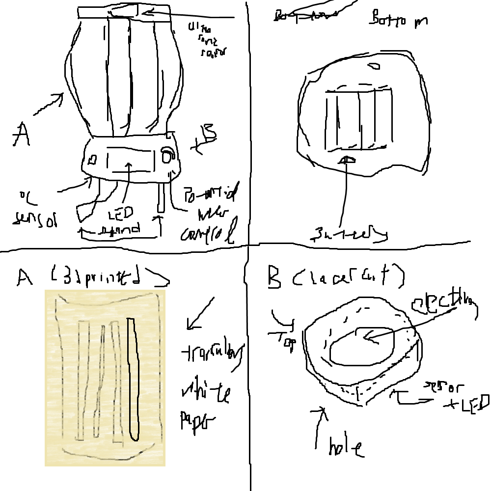
This was my first idea, after looking through several mood lamps online. As the A part of it is curved, and i intended it to be made of acrylic, i found that it was impossible to do it since I had no time to do it, due to my other projects. The B part was to be 3d printed. It has the idea of having a battery source in it, as I thought it would be good for it to be portable. The button, DHT sensor and LCD are at the front of the mood lamp, the LED inside the mood lamp, with some support from below.
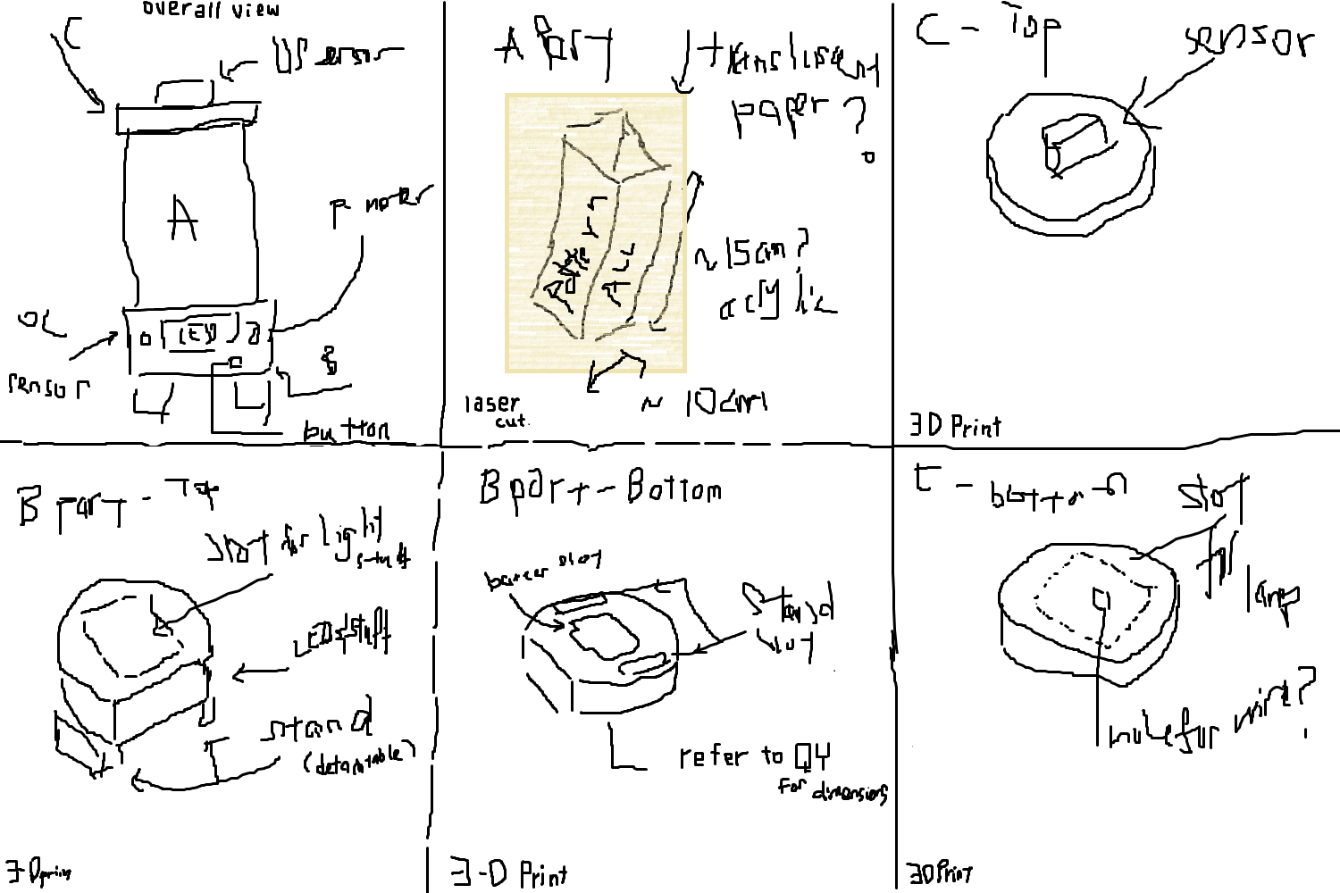
idea 2. This time, I made it such that the acrylic was all straight, no curved parts and a pattern engraved on it. The ultrasonic sensor would be at the top, with the acrylic cover being able to be slot in to Part B, the base of the mood lamp. Same as idea 1, the LCD, DHT sensor and button at the front, while the LED is inside the base. There is also support underneath the base.
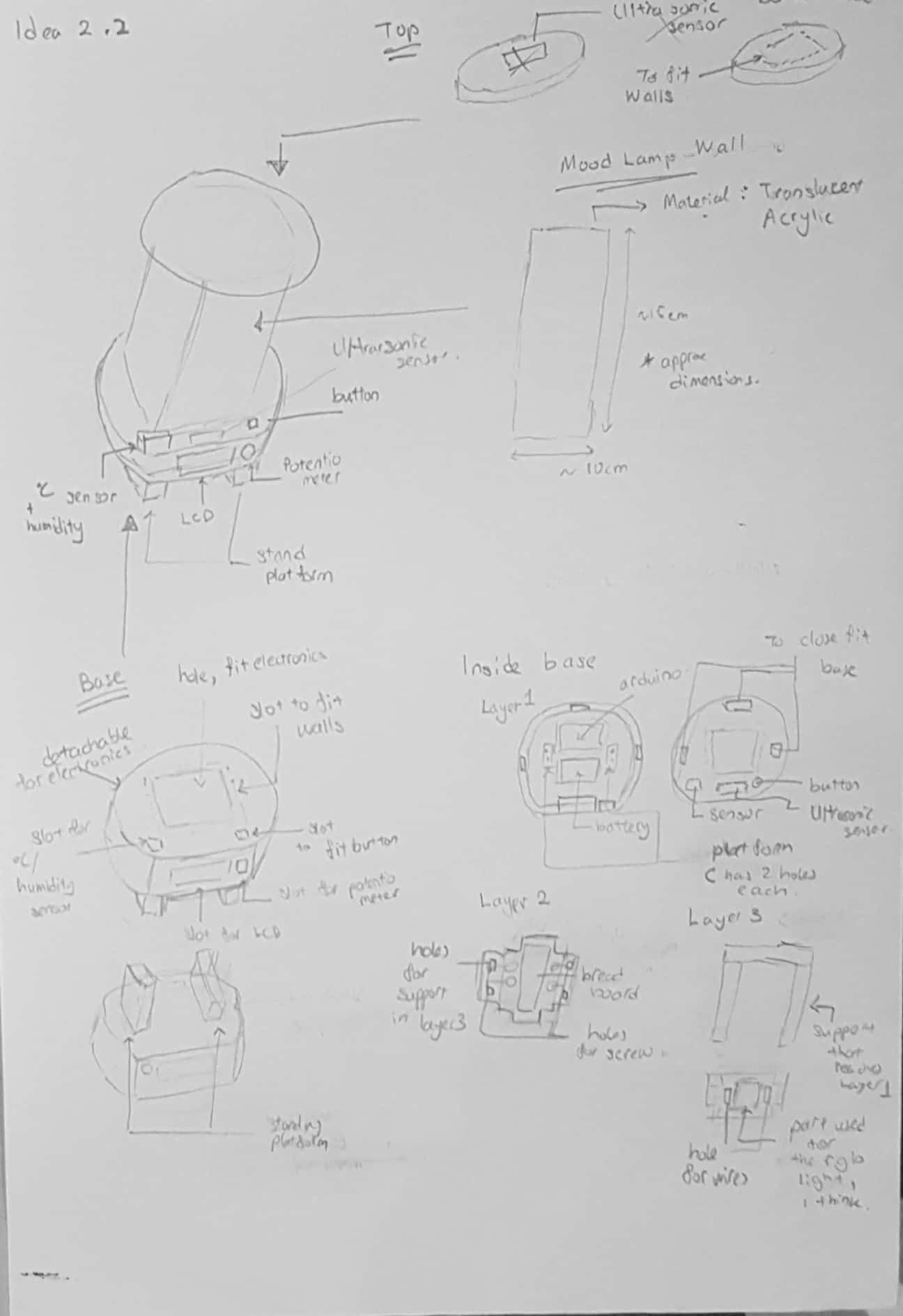
idea 3. the exterior is the same as idea 2, but this time the insides are elborated on, and instead of making the base round, it is instead sqaure/rectangle to allow more space. it is a multi-layer stacking where you gradually add items to each layer, where layer 1 is the bottom of the base, where it fits the arduino and battery. layer 2 fits the bread board, and some screws to secure it and holes for layer 3 to go through. the 3rd layer is made to fit the LED.
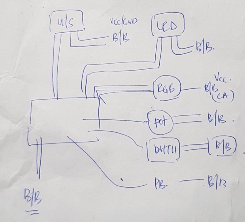
in the mean time, i came up with a circuit for the project. in the image: u/s = ultrasonic sensor, b/b = breadboard, vcc = source, gnd = ground, PB = push button, pot= potentiometer, rgb = rgb led, ca = cathode.
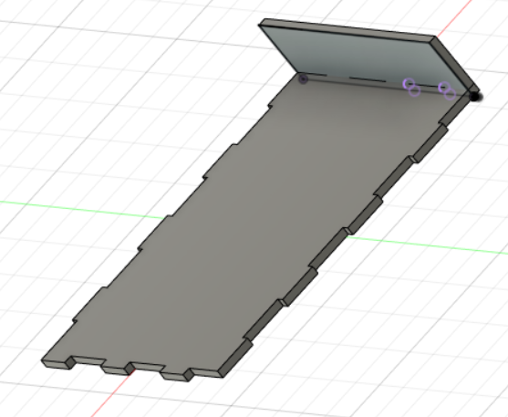
So at first, i tried to make the base out of laser cut, but i forgotten that i needed to make parts to secure the arduino board, breadboard and other devices, so i scrapped this model.
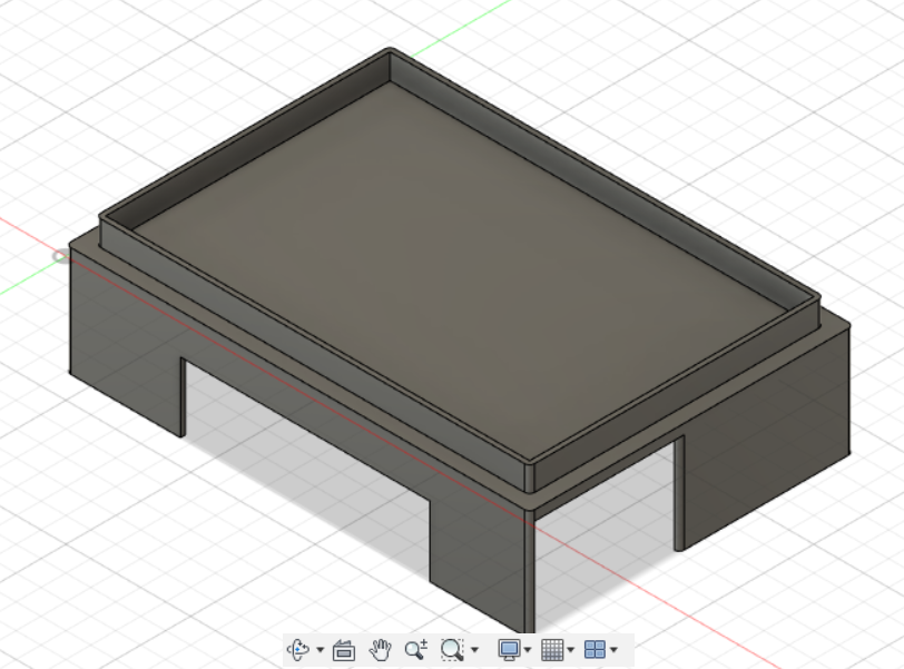
following my third idea, i tried to make a 2nd layer, but this kind of design is bound to fail as it has very little supports after I discussed with others about this.
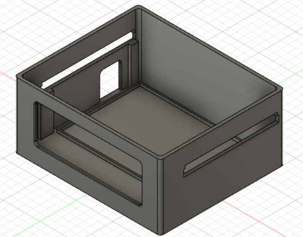
this is the base idea (finalized) for the model, without any securing for the LCD and Arduino Board. After that, i made a new save on a new model. (wow, i went 57 versions into this model)
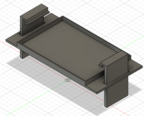
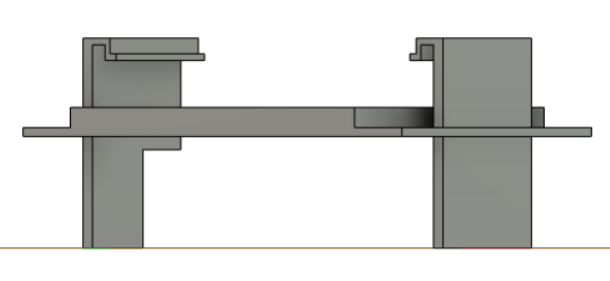
This is my finalized base model for the 2nd layer, after realizing what i can do to improve the model. I added in the hole in the base model of the base to accomodate for it.
After that, i worked on the laser cut parts to contain the ultrasonic sensor, DHT sensor and the main part of the mood lamp --- the translucent acrylic cover.
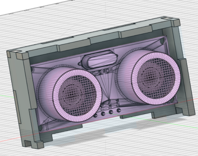
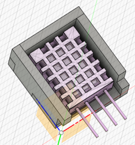
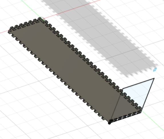
because i was experimenting with the parameters, i came up with a really messed up model to contain the rgb led, with 100 slots or so.
as such, i redid my model several days later, where i made a better version of the model.
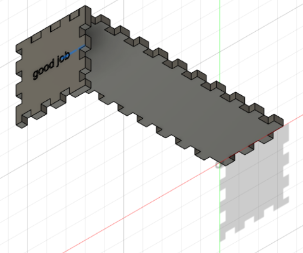
this model of the cover for the rgb led is better as all the long faces of this model are the same, allowing me to have 1 face to 4 sides.
by then , i finished my cover for the base.

when i printed the cover and base, i found out that i forgotten to include the securing parts for the lcd and the arduino board. on my 2nd printing of the base, i measured the securing points for the lcd wrongly, so i needed to reprint it. for my cover, i printed the wrong dimensions for the led cover and ultrasonic sensor, then adjusted it to be bigger because i forgotten to take into consideration of the wires pushing the layer up.


printed 2 parts to secure the layer 2, although it was unnecessary after wiring it, since the wires pushed the layer up to tighten it with the model.
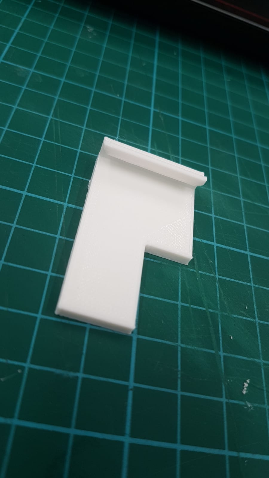
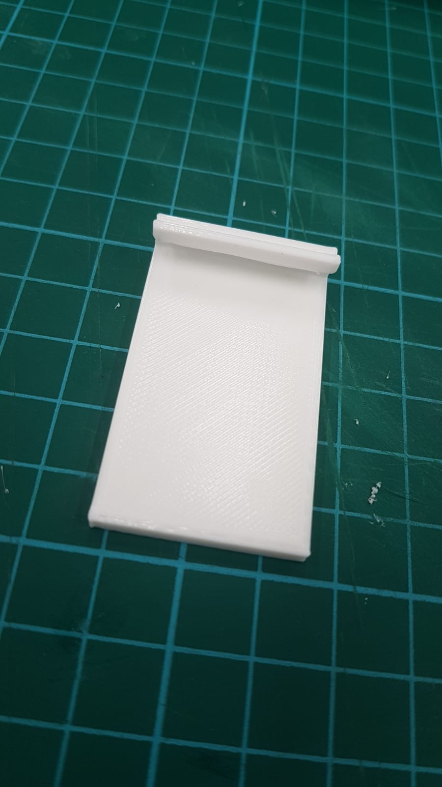
laser cut some covers for the devices that are exposed.
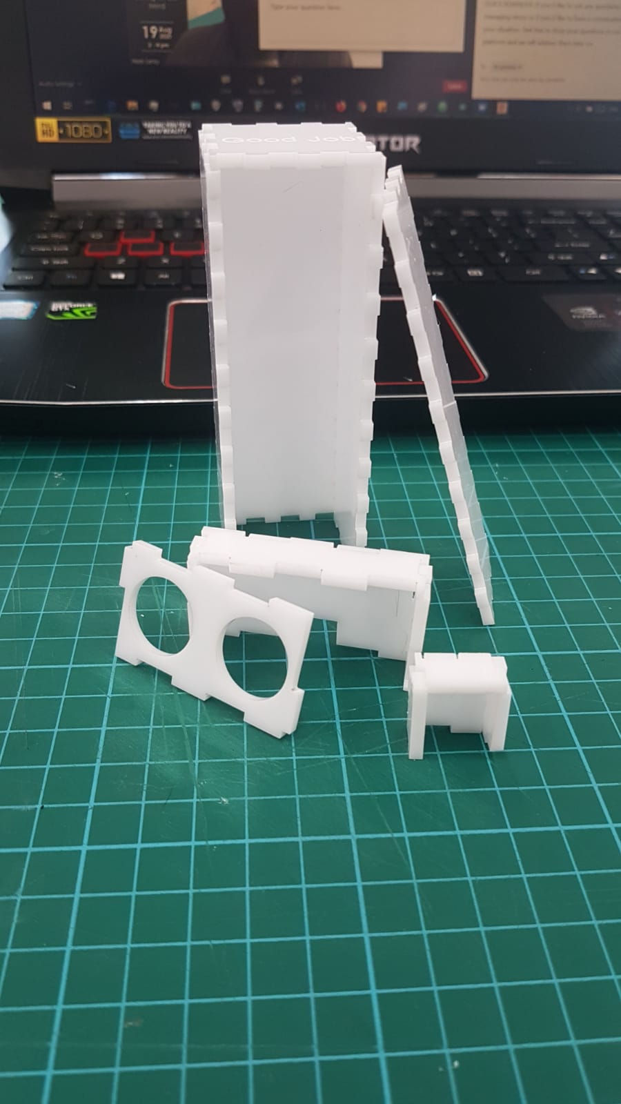
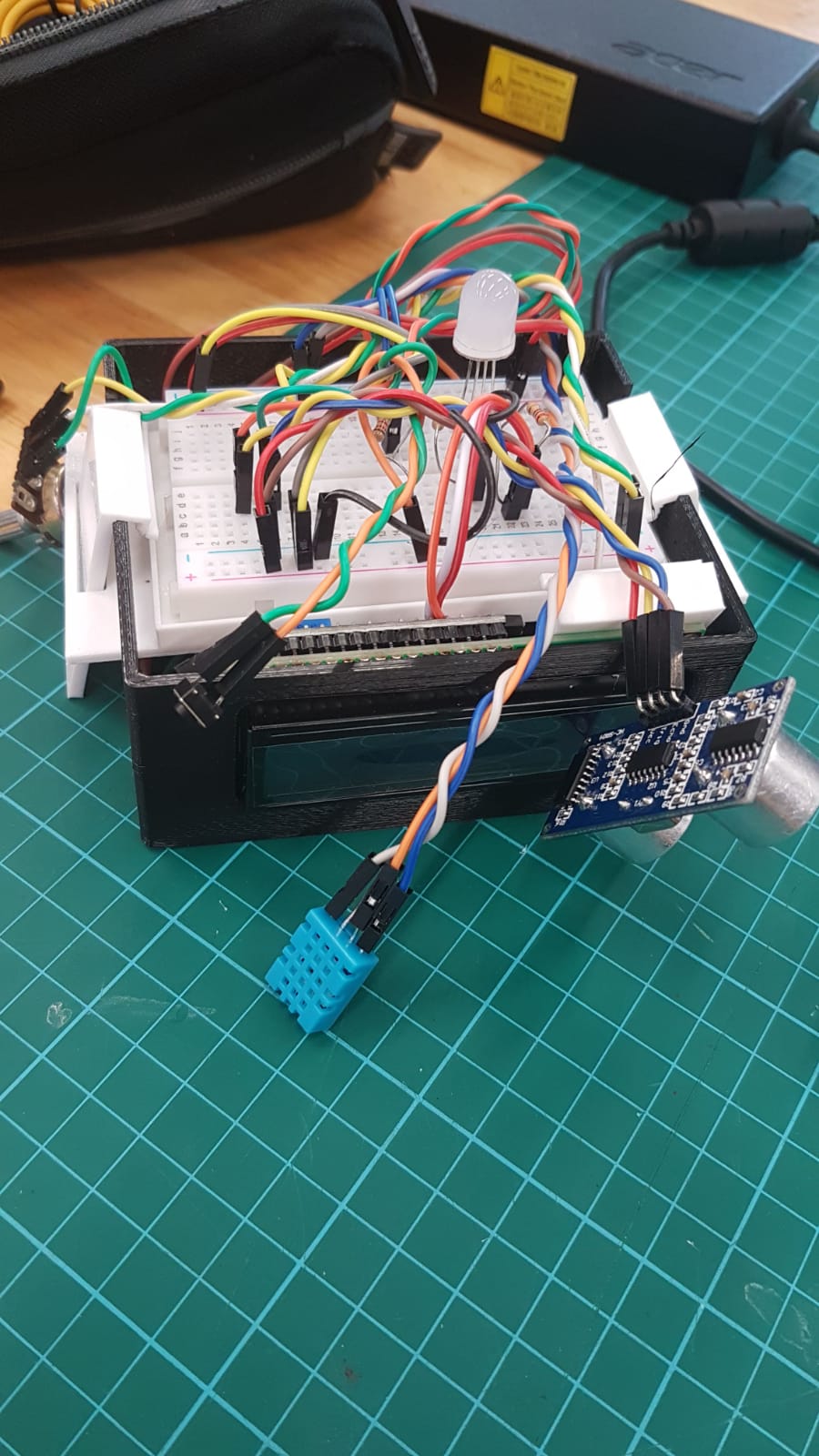
the wiring was pretty poorly done, since i didnt think about the wires in the creation of the models and it was too late to redo the design to incoporate the wires by then.
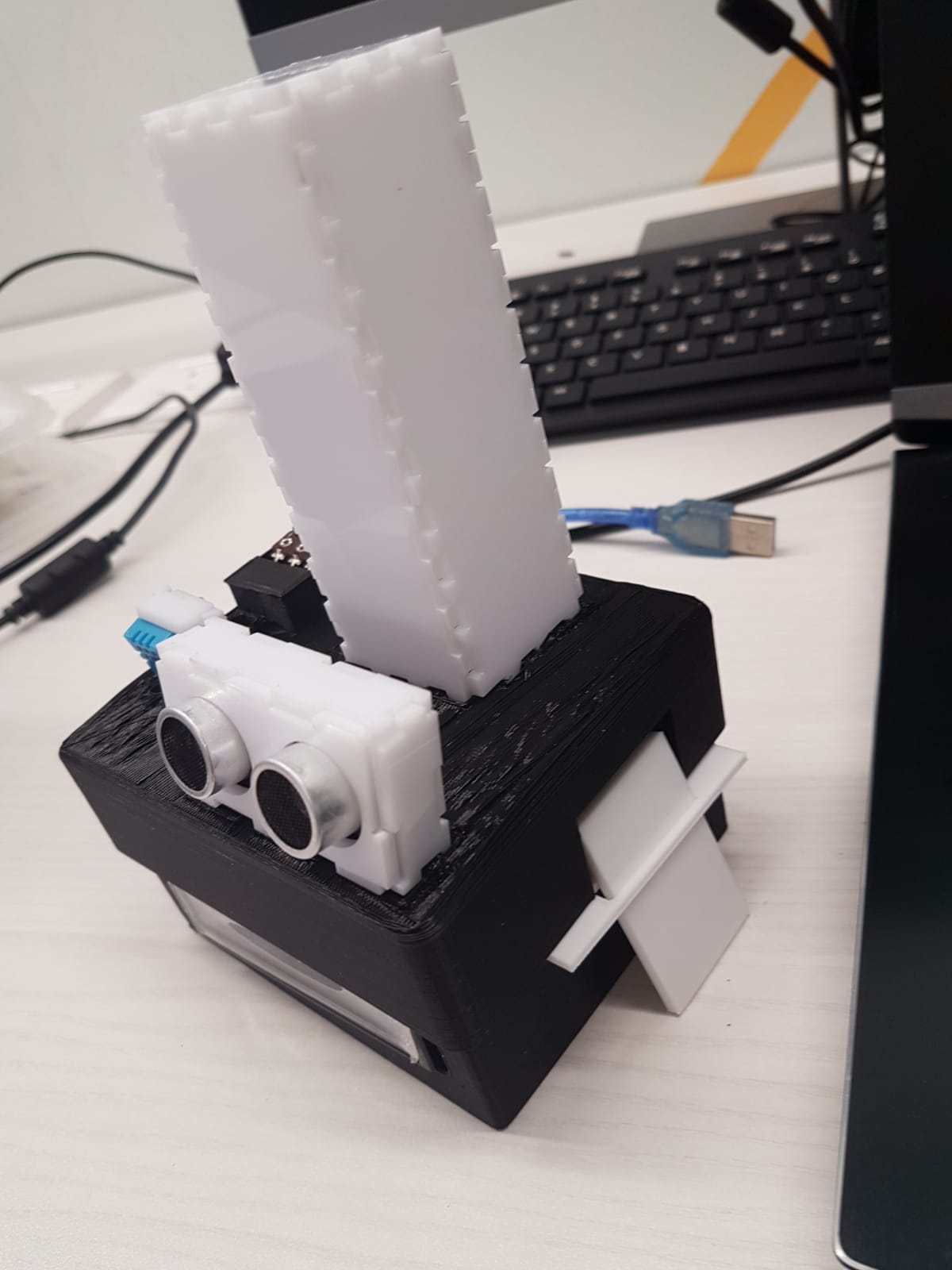
this is how the final model looks like, cover and base. after printing, it looks like this (did not take images of the final versions individually):
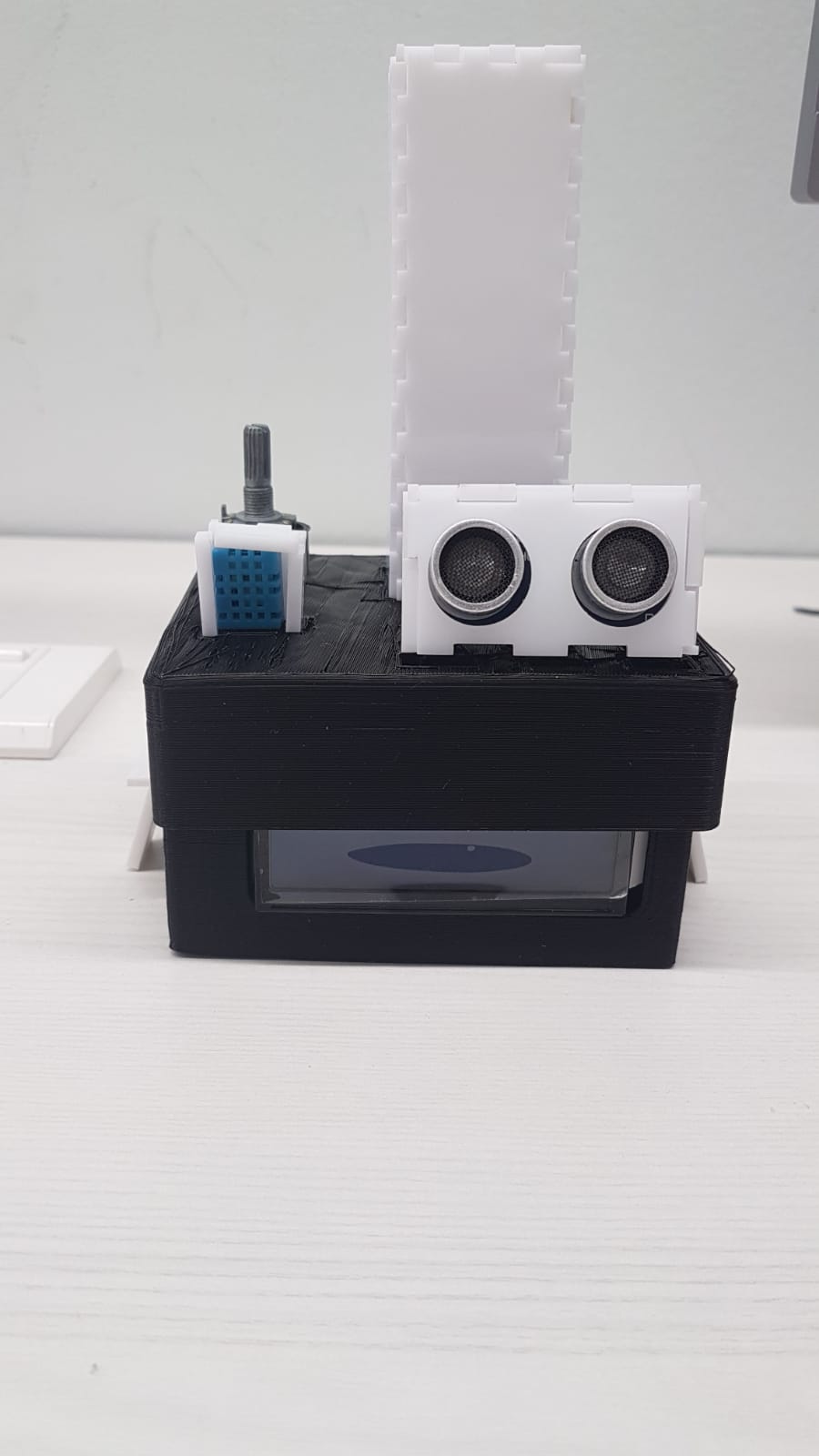
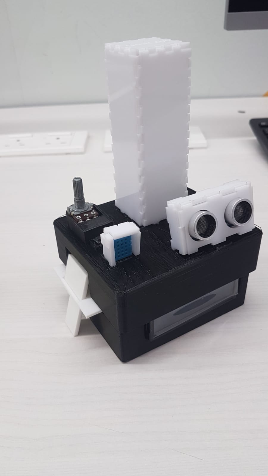
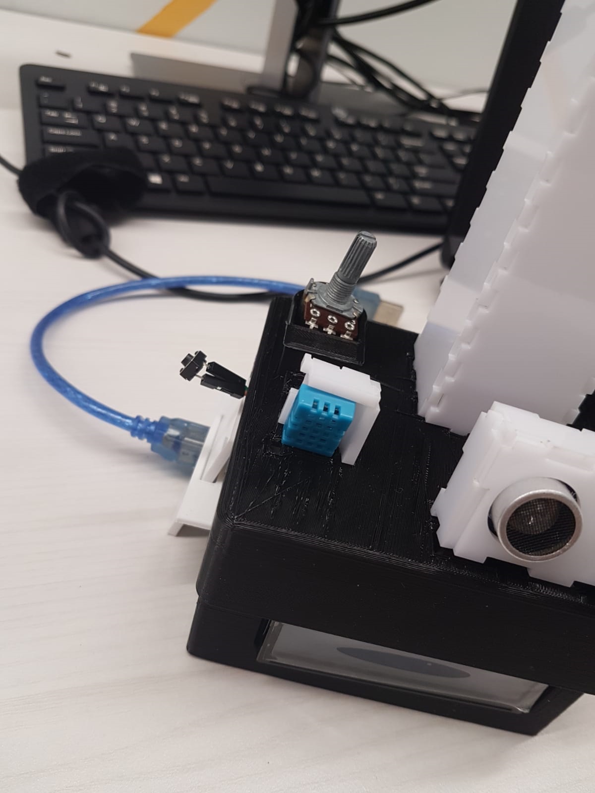
problems i encountered with wiring: it pushed my layer 2 upwards, so now it is very tight and hard to remove it when there is a loose wire. luckily (is it?), it is too tight to the point where the wires barely budge. another problem with it was that it was hard to do wire management and color coding. as such, i couldnt do much about it, so i twisted the wires together to remind myself "these wires go to the same device", like in this image (that will link you to this page, to the image i want to refer you to).
problems i encountered with designing: I didnt know what a mood lamp was, so I took a few days to come up with the ideas via googling. they didnt help as much as i thought it would, though they gave me a general idea on how it looks like. I was too hasty everytime i went to print, because i felt quite stressed at the unexpected events in one of my modules' group work, which i ended up doing practically everything myself. I was unable to measure the devices properly with a ruler, so i took some models from grabcad to use as reference models in the making of my laser cut and 3d print models. I did a mistake of using a 3mm translucent acrylic instead of a 2mm one, so i had to redo the parameters on my base. Because my idea was not easy to make via laser cut (i.e. extrusions on the base to secure arduino board and lcd), i had to look out for the secure points and restrict myself to 3d printing for making the base.
programming
As most parts of the program was already documented in the website (@arduino page of my website), i only needed to do one part of the program -- which was writing the logic to finish the setup for the mood lamp.
Here is the code that I wrote:
note: you need to have the DHT and the LCD libraries to make this work
wow, i made about 450 lines (since this was before i removed a few unnecessary lines)
variables that i declared
from the DHT example code, edits done: removed all code relating to degrees Fahrenheit, changed code about Serial.print to lcd.print
from ultrasonic sensor code, no changes as it was taught to me by my senior. removed code regarding Serial.print
void program "test", that runs during the setup to show the user what the current environment is like. also tests the condition of the dht and ultrasonic sensors of whether they can read the environment.
void programs "touch()" and "debounce()", where touch checks whether the button was pressed, and debounce to see if it was a long press (500ms). There is nothing done if there is a short press (less than 500ms)
void program "set()", that sets the end-user defined parameters for humidity, temperature and distance. if the upper limit is lower than the lower limit, the lcd will tell you that "upper >= lower" and forces you to re set it. Else, it will proceed unto the next setting, until you have done all 3 settings.
this part of the program checks the array, to display the respective colors
the actual main part of the program, where it reads from the sensors and lights up accordingly.
the setup of the program, where it declares the pinmode, initializes the lcd, starts the internal timer, starts the dht sensor, runs the void program test().
the part of the program that is looping endlessly. it really looks clean here, just because for some reason i wrote everything into mainprog().
video
since the video doesnt work for some reason, here's a google drive link to ithere are the files for the project; the code and a zip file of the models, f3d format

